
A TVS diode that clamps too late costs more than the part itself — it costs the MCU, the Ethernet PHY, or the USB-PD controller behind it. The most common surge-protection failures we see are not from undersized TVS parts; they come from parts that were almost right: VRWM too close to the bus voltage, clamping voltage ignored until the pulse hit, junction capacitance chosen without thinking about signal integrity. This guide walks through the six parameters that actually decide whether a TVS protects your circuit, with the numbers to target for each.
Why TVS Diodes Are Still the Default in 2026
Across board topologies, GDTs, MOVs, and TVS diodes all have a place — but for solid-state protection of low-voltage DC buses and high-speed signal lines, the TVS diode’s combination of sub-nanosecond response, predictable clamping, and small footprint keeps it at the center of the BOM. Industrial 24 V systems, USB-PD / Type-C 100 W charging rails, PoE Ethernet, automotive 12 V and 24 V buses, and 5G RF front-ends each rely on TVS arrays sized to their specific pulse environment. The risk is that “a TVS” is a vague specification — choosing the right one requires matching six numbers to your circuit, not picking the cheapest clamp.
Three trends are tightening the requirements in 2026:
- Higher bus voltages. USB-PD 3.1 Extended Power Range pushes 28 V, 36 V, and 48 V rails; TVS VRWM has to track.
- Faster signals. USB 3.2, HDMI 2.1, and 2.5 / 5 / 10 GbE Ethernet leave picosecond-level margin for added capacitance.
- Stricter automotive pulse testing. ISO 7637-2 and ISO 16750-2 load profiles expect TVS arrays that survive repeated transients without drifting.
A 6-Step Framework for Selecting a TVS Diode
1. Define the Operating Voltage of the Line You Are Starting From
Before any TVS spec, write down the maximum steady-state voltage the protected line ever sees — including tolerance and ripple. For a USB-PD source that advertises 20 V, the line can reach 21 V under load transients; for a 24 V industrial bus with 10% tolerance, plan for 26.4 V; for a 12 V automotive rail, ISO 16750 allows 18 V during jump-start. The TVS VRWM must clear all of these with margin.
2. Set VRWM Just Above the Maximum Bus Voltage
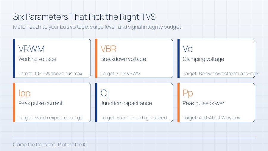
VRWM (Working Maximum Reverse Voltage, sometimes called Vr or Vwm) is the maximum continuous DC voltage the TVS will see without conducting. The rule of thumb: VRWM should be at least 10–15% above the maximum bus voltage, and never below it. A 5 V signal line on a 5% tolerance supply can reach 5.25 V — pick a 6 V or 6.5 V VRWM TVS, not a 5 V one.
3. Choose VBR as the Trigger Threshold Above VRWM
VBR (Breakdown Voltage, sometimes called Vbd) is the voltage at which the TVS starts to conduct heavily during a transient. It is typically ~1.1× VRWM. Pick a part whose VBR comfortably sits above VRWM but below the absolute maximum rating of the downstream IC. If the device behind the TVS is rated to 30 V abs max, VBR in the 24–27 V range gives a clean trigger window.
4. Match Clamping Voltage to Downstream Survivability
Vc (Clamping Voltage) is the voltage the TVS holds across itself during a defined peak pulse current (Ipp). This is the number that decides whether the MCU, USB controller, or Ethernet PHY survives. The TVS datasheet plots Vc at multiple Ipp points; pick a device whose Vc at the relevant Ipp is below the abs-max of the protected part, with margin. Clamping voltage is the single most-misread spec — a TVS with a low VRWM but a high Vc at your pulse current will not protect anything.
5. Watch Junction Capacitance on High-Speed Lines
Cj (Junction Capacitance) is the parasitic capacitance across the TVS. For DC power rails it usually does not matter; for USB 2.0, USB 3.x, HDMI, and 2.5 / 5 / 10 GbE Ethernet, it directly degrades signal integrity. Look for the Cj value at the relevant bias voltage (often 0 V or 2.5 V) and compare against the channel budget. A 100 pF TVS is fine on a 24 V industrial bus; a 100 pF TVS on a USB 3.2 SuperSpeed pair will fail compliance. Low-capacitance TVS arrays trade clamping performance for sub-1 pF Cj.
6. Select Package and Power Rating for the Energy You Must Absorb
Pp (Peak Pulse Power, typically 8/20 µs or 10/1000 µs waveform) defines how much energy the TVS can sink in a single pulse without failing. Common ratings: 400 W, 600 W, 1000 W, 1500 W, 4000 W. Match the package and power rating to the surge environment: indoor consumer products see modest pulses; outdoor industrial and automotive see direct lightning-induced transients where 1500 W or higher is normal. A larger package also helps thermal dissipation for repeated pulses.
TVS Parameters at a Glance
| Parameter | Symbol | What It Means | Typical Target |
|---|---|---|---|
| Working voltage | VRWM | Max continuous DC without conduction | 10–15% above bus max |
| Breakdown voltage | VBR | Trigger threshold for conduction | ~1.1× VRWM, below protected IC abs-max |
| Clamping voltage | Vc | Held voltage at peak pulse current (Ipp) | Below downstream abs-max with margin |
| Peak pulse current | Ipp | Pulse current the TVS survives | Match to expected surge level |
| Junction capacitance | Cj | Parasitic C across the device | Sub-1 pF for high-speed signal lines |
| Peak pulse power | Pp | Energy per 8/20 or 10/1000 µs pulse | 400–4000 W by environment |
TVS Selection Checklist
- Bus voltage defined including tolerance, ripple, and transient overshoot.
- VRWM set at least 10–15% above the maximum continuous voltage.
- VBR comfortably above VRWM and below the protected IC abs-max.
- Clamping voltage (Vc) verified at the actual Ipp, not at the headline rating.
- Junction capacitance (Cj) checked against the signal-integrity budget at operating bias.
- Peak pulse power (Pp) matched to the surge environment (8/20 µs or 10/1000 µs).
- Package sized for thermal dissipation over the expected pulse repetition rate.
- Pulse-test standard (IEC 61000-4-2, ISO 7637-2, ISO 16750-2) referenced in the BOM notes.
Frequently Asked Questions
Unidirectional or bidirectional TVS — which one?
Unidirectional TVS is the lower-clamping-voltage choice for DC rails where the polarity is fixed; bidirectional TVS is required on AC-coupled signal lines or any line that swings both polarities around ground. The trade-off is slightly higher capacitance on the bidirectional part for the same voltage class.
Is an automotive-grade TVS always necessary for industrial designs?
Not always, but automotive-grade parts are specified over wider temperature ranges (-40 to +150 °C vs -40 to +85 °C) and against stricter pulse standards. If your industrial product ships to outdoor enclosures, vehicle-charging stations, or any environment with direct lightning exposure, paying the small premium for AEC-Q101-qualified TVS is worth it.
TVS vs MOV vs GDT — when does each win?
MOVs handle higher energy at the cost of slower response and wear-out after multiple hits; GDTs handle very high currents but do not clamp low voltages well. TVS wins on response time and on integration with solid-state circuits at low voltages. A common pattern is a GDT at the boundary, a TVS at the IC — each doing what it does best.
Do I still need a TVS if I already have a PTC fuse?
A PTC fuse limits over-current; it does not clamp over-voltage. The two protect against different failure modes and are almost always used together: TVS clamps the transient, PTC limits sustained over-current, and the downstream IC sees a survivable event.
Putting It Into Practice
Pick the three most exposed connectors on your design — the DC input, the outdoor-rated port, the high-speed data line — and run each through the six parameters above. Use the relevant pulse standard as the surge budget, then look at the Vc — at your Ipp — rather than at VRWM alone. For ready-to-ship TVS arrays from leading protection-device manufacturers, browse our Circuit Protection catalog, or submit an RFQ with the bus voltage, expected surge level, and signal-integrity budget and we will spec the right part alongside the BOM.
ICSmooth supplies authentic TVS diodes and circuit-protection components from leading manufacturers, with full datasheet traceability and rapid sourcing across franchised and excess channels. Submit an RFQ or browse the Circuit Protection catalog to start a qualified conversation.


