
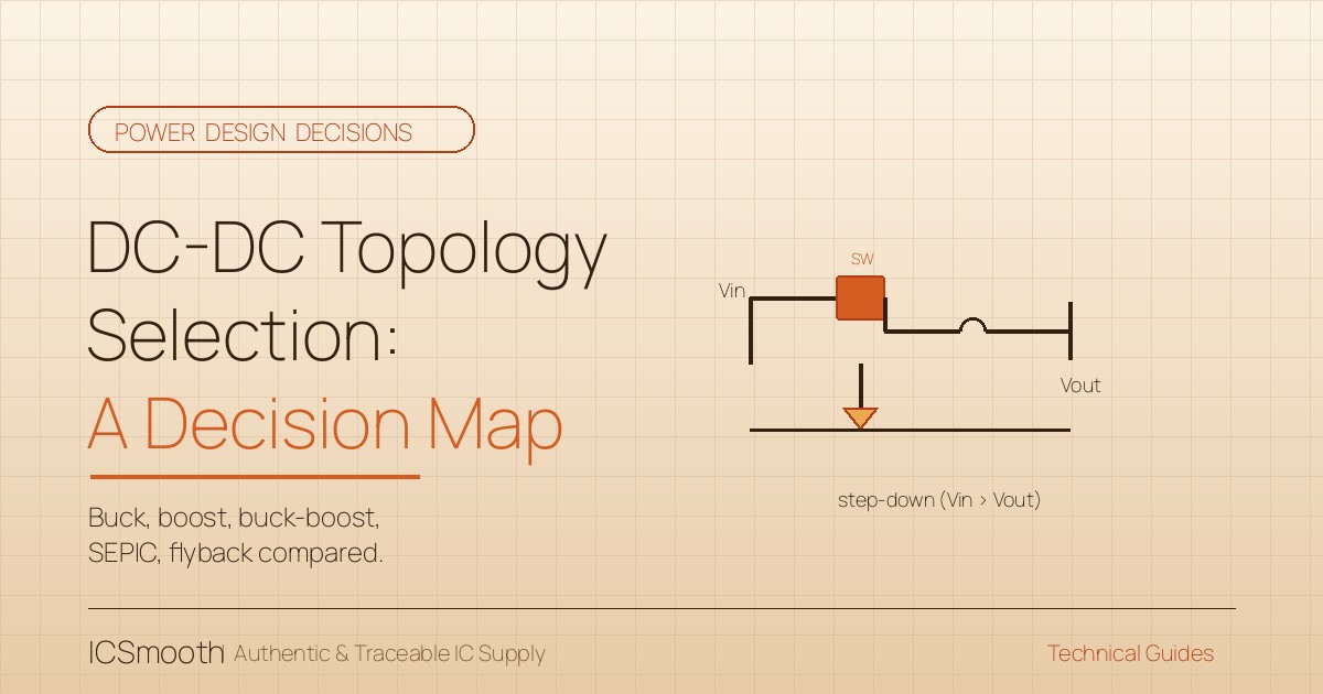
Pick the wrong DC-DC topology and the rest of the power stage is fighting uphill: the magnetics end up oversized, the switch losses climb, the EMI filter grows, and the BOM cost drifts above the target before the design is even frozen. The five workhorse topologies — buck, boost, buck-boost, SEPIC, and flyback — cover most low-to-medium power designs, but each one assumes a specific relationship between input and output. This guide maps that relationship so the topology choice follows from the rail requirements, not from habit.
Why the Topology Choice Comes First
Everything downstream — the inductor, the capacitor bank, the switch rating, the EMI strategy — derives from the topology. Choosing the topology after the inductor is sized is a common rework trigger, and rework on the power stage is the most expensive rework on the board. The first decision in any DC-DC design is not “which controller IC.” It is “which topology fits the rail relationship I actually need.”
Three rail relationships cover most designs:
- Vin always above Vout — buck is the natural fit. Step down, single switch, smallest magnetic for the power level.
- Vin always below Vout — boost is the natural fit. Step up, single switch, output ripple harder to filter than buck.
- Vin above and below Vout at different operating points — buck-boost, SEPIC, or flyback territory, with a real tradeoff among them.
Topology Decision Map
| Topology | Rail Relationship | Best For | Watch Out For |
|---|---|---|---|
| Buck (step-down) | Vin > Vout, always | Most point-of-load conversions, USB-PD, server rails | Minimum on-time limits step-down ratio at high frequency |
| Boost (step-up) | Vin < Vout, always | Battery boosting, LED drive, low-voltage rails | Output ripple higher than buck; no short-circuit protection inherently |
| Buck-boost (non-inverting) | Vin crosses Vout | Battery-powered devices, USB-OTG, wide-input industrial | Two switches; control loop is harder than buck |
| SEPIC / Cuk | Vin crosses Vout | Automotive where input can spike and sag around 12 V | Coupling capacitor or inductor adds BOM and complexity |
| Flyback (isolated) | Any relationship, with isolation | AC-DC front end, isolated DC-DC, safety-required rails | Transformer design is non-trivial; leakage inductance shapes snubber choice |
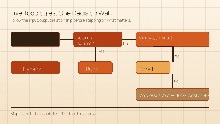
A Decision Walk for Picking the Topology
1. Establish the Input-to-Output Relationship First
List every operating point: nominal, minimum under transient, maximum under load-dump or input-surge, and any cold-start condition. A battery that runs from 9 V to 16 V while delivering 12 V out is buck-boost territory; the same battery delivering 5 V out can stay buck across most conditions. The answer set narrows as soon as you write down the worst-case range.
2. Decide Whether You Need Isolation
Isolation is a regulatory question, not a preference. If the output must meet a safety standard (medical, industrial where the user can touch the output, AC-DC adapters), flyback or a forward topology enters the conversation. For point-of-load on a board that is already isolated upstream, you can stay non-isolated and save the transformer.
3. Quantify the Switching Frequency
Higher frequency shrinks the magnetics, at the cost of higher switching loss and a more demanding EMI filter. The chosen topology sets a practical ceiling: buck and boost go high easily; SEPIC and flyback typically run lower because the magnetics design gets harder at frequency. Pick the topology first, then choose the frequency to fit the magnetic size target.
4. Check the Switch Stress
Each topology puts a specific voltage and current stress on its switches. A boost switch sees Vout when it opens; a buck-boost switch sees Vin + Vout; a flyback switch sees Vin plus the reflected output. Choose the topology with margin to spare, then size the switch. If the switch stress forces a more expensive part than the rest of the BOM, the topology may not be the right one.
5. Validate Efficiency Against the Thermal Budget
Efficiency is not just a number — it sets the thermal dissipation that determines enclosure size, fan requirements, and reliability. Before you choose the topology, run the efficiency math at your operating point, not at the headline efficiency from a marketing datasheet. Two candidates that look similar on paper can differ by enough efficiency to flip the thermal design.
DC-DC Topology Checklist
- Input-to-output range mapped across nominal, minimum, and worst-case transient conditions.
- Isolation requirement confirmed against the applicable safety standard.
- Switching frequency chosen to fit the magnetics size target.
- Switch stress computed, with margin against the rated VDS / VCE.
- Efficiency at operating point estimated and thermal budget verified.
- Topology reference design sourced from the controller IC vendor before schematic freeze.
- Second-source controller IC identified in case the primary tightens.
Frequently Asked Questions
Can I just use a buck for everything by lowering Vin?
You can, but pre-regulating Vin costs you an extra stage, additional magnetics, and additional efficiency loss. If Vin crosses Vout across operating conditions, a buck-boost or SEPIC is usually a smaller and more efficient solution than a buck behind a pre-regulator.
SEPIC vs buck-boost — when does SEPIC win?
SEPIC handles a wider Vin range with a cleaner input-current waveform than a non-inverting buck-boost, and it tolerates short-circuit at the output. Buck-boost has fewer parts. The decision usually comes down to the input-current profile your upstream rail can supply and whether you can tolerate the additional coupling capacitor.
When do I reach for a flyback instead of a SEPIC?
Whenever you need isolation between input and output — safety, ground separation, or a regulatory barrier. Flyback adds a transformer, but it is the right answer when isolation is non-negotiable.
How does controller IC choice interact with the topology?
Tightly — most controllers are built around one or two topologies. A buck controller does not run a SEPIC. Choose the controller family from the same vendor that publishes the reference design for your chosen topology, and your first-pass risk drops sharply.
Component Sourcing Implications of the Topology Decision
The topology choice is upstream of the BOM, but it is also upstream of the sourcing strategy. A buck-only design typically pulls from a wide catalog of controllers, MOSFETs, and gate drivers with mature multi-vendor support — sourcing is straightforward, lead times are predictable, and second sources are easy to qualify. A flyback design pulls from a narrower catalog and adds a transformer in the BOM, with its own supplier base and its own qualification work. A SEPIC sits in between but adds a coupling capacitor that you have to source and characterize. As you move right on the topology complexity axis, you trade BOM simplicity for sourcing complexity, and the lead-time picture you need to manage gets wider too. Plan that into the RFQ before the schematic freeze rather than after.
Putting It Into Practice
Take your most demanding rail — the one with the widest input range, the tightest efficiency target, or the strictest isolation requirement — and run the five-step walk above before opening the controller datasheet. The answer will fall into one of the five topology rows, and from there the controller choice, magnetics, and EMI strategy follow. For DC-DC controllers, MOSFETs, gate drivers, and the surrounding power-management components, browse discrete semiconductors or submit an RFQ with your rail specifications and we will spec the topology and its parts together.
ICSmooth supplies authentic power-management ICs, MOSFETs, gate drivers, and discrete components from leading manufacturers, with full traceability and dual-channel sourcing across franchised and excess inventory. Submit an RFQ or browse our discrete semiconductor catalog to lock the topology before you freeze the design.


